





Electric Aircraft Hydrant Dispensers vs Diesel Models: Operational Cost and Emission Comparison
 Aug 27, 2026|
 The Shift Toward Zero-Emission GSE: 2026 Airport Requirements
A 100% electric hydrant dispenser removes diesel combustion at the vehicle exhaust, reducing local NOx, particulate matter, CO₂ and engine noise on the apron. The engineering trade-off is transferred from fuel consumption and engine maintenance to battery capacity, charging power, thermal management and electrical safety.
For a typical hydrant dispenser operating at 1,500–2,500 L/min, the fuel-flow requirement itself does not dictate whether the vehicle should use a diesel or electric powertrain; the key variables are pump efficiency, required differential pressure, duty cycle, battery usable energy and charging strategy. EI 1540, 6th edition, now explicitly includes battery-powered vehicles and greenhouse-gas reduction considerations in aircraft fueling facility guidance.
Environmental Regulations and EI 1540 Requirements
Airport operators are increasingly separating two issues that are often combined in fleet discussions:
Tailpipe emissions - eliminated during operation by a battery-electric vehicle.
Lifecycle emissions - dependent on electricity generation, battery production and battery replacement.
Therefore, the correct engineering statement is zero tailpipe-emission GSE, rather than automatically claiming zero lifecycle CO₂.
For airports operating under local air-quality restrictions, electric hydrant dispensers can remove diesel exhaust directly from the aircraft stand. This is particularly relevant in enclosed or semi-enclosed fueling areas, maintenance zones and terminals where repeated diesel operation creates both exhaust and acoustic exposure.
Electrical equipment used around aviation fuel must still satisfy the hazardous-area classification specified by the installation. IECEx guidance identifies Zone 1 as an area requiring equipment suitable for an explosive atmosphere that may occur during normal operation.
The vehicle's high-voltage traction system, charging equipment and control cabinets must therefore be assessed separately from the fuel-handling components. A battery-electric powertrain does not remove the need for correct bonding, grounding, isolation, emergency shutdown and fuel-vapor risk controls.
Total Cost of Ownership at 8–10 Years: Diesel vs Electric
The useful TCO comparison is not simply diesel price versus electricity price. A fleet calculation should include energy, scheduled maintenance, battery degradation, charging infrastructure, downtime and residual value.
| Cost item | Diesel hydrant dispenser | Battery-electric hydrant dispenser |
|---|---|---|
| Primary energy source | Diesel fuel | Grid electricity |
| Tailpipe emissions | CO₂, NOx, particulate matter | None during vehicle operation |
| Engine oil and filters | Required | Not applicable to traction motor |
| Diesel engine cooling system | Required | Battery/motor thermal management |
| Exhaust after-treatment | May include DPF/SCR/EGR depending on engine | Not applicable |
| Routine drivetrain maintenance | Higher component count | Lower mechanical component count |
| Refueling/energy replenishment | Diesel tank or external fueling | AC/DC charging system |
| Long-shift operation | High energy-storage density | Depends on battery capacity and duty cycle |
| Charging downtime | None for conventional diesel refueling | Must be included in fleet scheduling |
| Battery degradation | Not applicable | Must be modeled over service life |
| Local exhaust emissions | Present | Zero tailpipe emissions |
| Apron noise at idle | Engine noise | Substantially reduced |
| Infrastructure requirement | Diesel storage/fueling | Electrical capacity and charging stations |
For procurement, calculate cost per operating hour and cost per aircraft fueling cycle, not only cost per kilometer. Hydrant dispensers can spend long periods stationary while operating pumps, controls, communication systems and auxiliary equipment. That makes auxiliary electrical consumption and hydraulic pump efficiency relevant to the TCO model.
Insert Link: Aircraft Refueler & Hydrant Dispenser Catalog
Technical Comparison of Electric vs Diesel Hydrant Dispensers
The fuel-delivery architecture can remain similar between electric and diesel models. Both can use a hydrant pit coupler, pressure control system, fuel meter, filter/water separator, deadman control switch, bonding reel and emergency shutdown circuit.
The primary difference is the energy source driving the hydraulic system and auxiliary electrical loads.
Battery Endurance and Charging Infrastructure: 300–600 kWh Design Range
Battery sizing should be calculated from the actual shift profile rather than vehicle mass alone.
A simplified calculation is:
Required battery energy = average electrical load × operating time ÷ usable battery depth of discharge
For example, if the complete vehicle averages 35 kW during a 10-hour duty period:
35 kW × 10 h = 350 kWh
If the fleet design limits usable battery energy to 80%:
350 ÷ 0.80 = 437.5 kWh nominal battery capacity
This is only an engineering example. Actual consumption varies with pump duty, hydraulic pressure, ambient temperature, HVAC load, auxiliary equipment, vehicle speed, battery temperature and charging losses.
For airport fleets, a practical electric hydrant dispenser specification should therefore identify:
- Battery nominal voltage
- Gross and usable kWh
- Continuous and peak motor power
- Maximum DC charging power
- Charging connector standard
- Charging time from defined SOC levels
- Battery operating temperature range
- Thermal-management method
- Emergency isolation procedure
- IP rating of exposed electrical assemblies
- Battery warranty and replacement criteria
A 400 kWh battery charged at an effective 200 kW power level cannot be treated as a simple two-hour charging calculation in actual fleet planning because charging power normally changes with state of charge and battery temperature.
The charging station must also be sized against the airport's available electrical capacity. Multiple dispensers charging simultaneously can create a significant peak load.
For a fleet of five vehicles, each drawing 200 kW simultaneously, the theoretical instantaneous charging load is:
5 × 200 kW = 1 MW
This figure excludes charger losses, building loads, transformer constraints and load-management margins.
Pumping Performance and Flow Rate Stability: 1,500–2,500 L/min
Electric propulsion does not automatically improve fuel-flow performance. Flow stability depends on the complete hydraulic system:
- Pump curve
- Motor speed control
- Pump efficiency
- Fuel viscosity
- Filter differential pressure
- Hydrant pressure
- Pressure-control valve response
- Hose and pipe pressure loss
- Meter characteristics
- Deadman control logic
For example, if the system requires 2,000 L/min, the pump must be selected for the required flow at the specified differential pressure rather than simply selecting a motor based on nominal horsepower.
A variable-frequency or electronically controlled electric motor can provide precise speed regulation. This can reduce abrupt pump-speed changes and improve pressure control when the system is correctly tuned.
The same principle applies to the spring-return fail-safe valve and pressure-control architecture. Loss of control power should produce the specified safe valve position rather than an uncontrolled fuel-flow condition.
Hydrant system components should be evaluated against the applicable edition of EI 1584. The current fifth edition specifies recommended minimum mechanical and performance requirements for four-inch hydrant pit valves and hydrant pit couplers and addresses interchangeability between manufacturers.
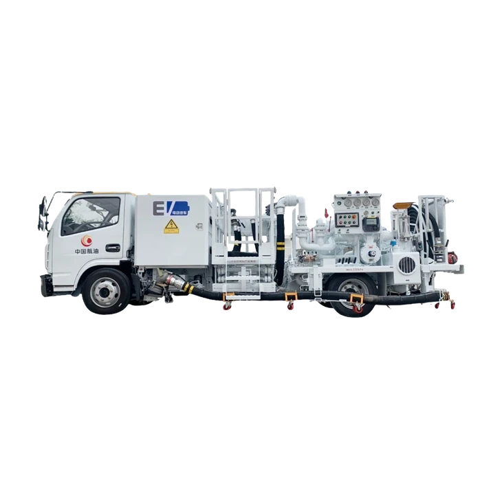
Key Benefits of 100% Electric Hydrant Dispensers: 0 Tailpipe Emissions
The strongest engineering case for electric hydrant dispensers is not simply lower fuel cost. It is the reduction of combustion-engine systems on a vehicle whose primary operating function is stationary fuel transfer.
Reduced Maintenance and Apron Noise: Fewer Engine Service Items
A diesel hydrant dispenser contains an internal-combustion engine, lubrication system, cooling system, fuel injection system, exhaust system and associated emissions-control hardware.
A battery-electric model removes the combustion engine and therefore eliminates engine oil changes, diesel fuel filters, exhaust after-treatment maintenance and several engine-related failure modes.
This does not mean an electric dispenser is maintenance-free.
The maintenance program shifts toward:
- Battery state-of-health monitoring
- High-voltage insulation checks
- Motor and inverter inspection
- Cooling-system inspection
- Charging connector maintenance
- Brake and suspension service
- Tire inspection
- Fuel-system inspection
- Deadman control verification
- Static bonding continuity testing
- Emergency shutdown testing
- Hydrant coupler inspection
The fuel-handling side remains subject to the same contamination-control requirements regardless of powertrain.
For filter/water separators, the applicable reference is EI 1581. The current seventh edition specifies minimum laboratory performance, mechanical requirements and qualification procedures for aviation fuel filter/water separators.
A filter separator that meets the required fuel-quality specification does not become less important because the dispenser is electrically powered.
Electric Motor Controls and Fueling Safety: Fail-Safe Shutdown Logic
Electric powertrains offer precise electronic control, but electronic control must not replace independent safety functions.
A properly engineered hydrant dispenser should maintain a defined shutdown chain incorporating the:
Deadman control switch → control logic → spring-return fail-safe valve → pump shutdown → emergency shutdown circuit
The exact architecture depends on the vehicle and project specification.
The Deadman control switch should require continuous operator action during fueling. Releasing the switch should initiate the defined shutdown sequence rather than leave the fuel-delivery system operating.
The electrical system should also provide appropriate isolation between high-voltage propulsion circuits and low-voltage control circuits.
Fueling equipment may incorporate:
- Emergency stop switches
- Deadman control
- Static bonding reel
- Interlock circuits
- Pump permissive logic
- Hydrant pit coupler interlocks
- Overpressure protection
- High-voltage isolation monitoring
- Battery emergency disconnect
- Charging interlock
Where equipment is installed in a classified hazardous area, the applicable ATEX or IECEx certification must correspond to the actual equipment location and protection concept. IECEx documentation identifies Zone 1 with Equipment Protection Level Gb or Ga as applicable to the equipment protection concept.
The electric drivetrain itself should not be described as "explosion-proof" unless the specific component has the required certification. Hazardous-area compliance is a certification attribute of the equipment and installation, not a generic property of an electric vehicle.
Aircraft Refueler and Hydrant Dispenser Product Range
Selecting an Electric Hydrant Dispenser for Airport Fleet Deployment
The correct electric hydrant dispenser is determined by duty cycle, hydrant pressure, required flow, battery capacity and charging availability.
A procurement specification should define the operating envelope before comparing manufacturers.
2,000 L/min Hydrant Duty: Start With the Hydraulic Load
The first technical question should be:
What flow rate and differential pressure must the dispenser maintain simultaneously?
For example, a specification requiring 2,000 L/min at a defined downstream pressure should be evaluated using the complete pump curve and hydraulic-loss calculation.
The calculation should include:
Hydrant pressure + pump differential pressure − filter loss − valve loss − hose loss − meter loss = available aircraft-side pressure
The remaining pressure must stay within the aircraft fueling system's permitted range.
A high-power electric motor does not compensate for an incorrectly selected pump. Oversizing the motor can increase battery consumption without improving useful fuel delivery.
EI 1581 Filter Separation: Verify Qualification, Not Marketing Claims
If the dispenser incorporates a filter/water separator, procurement documentation should identify the exact equipment configuration and qualification basis.
EI 1581 covers filter/water separators used throughout aviation fuel supply systems and includes categories for commercial jet fuel, military jet fuel and specified military fuel with thermal-stability additive.
Do not treat a generic industrial filter as equivalent to an aviation fuel filter/water separator simply because the housing pressure rating is sufficient.
The purchaser should request: